Imperfect Process leads to Sub-optimum Results
Automotive Plant Layout and Planning has been a challenging problem with diverse and often conflicting goals. OEMs seek to achieve space optimization, minimum no. of equipments (for lower cost), optimal Robots’ utilization and higher production rate, all at the same time. Their engineering teams rely on domain experts who come up with and initial hypothetical solution (may be this is based on a previous similar existing solution or a completely new idea) which is then evaluated against the program metrics and if they are not met, the solution is optimised and thus the initial solution keeps on getting optimised until a workable solution is reached. Once an acceptable solution is found, no further attempt may be made to see if a better solution exists.
Further complexity is added when the product development team changes the panel data, the joining definition and often, also, the build process. This entire process gets really time consuming and wasteful in situations where this plant engineering activity is outsourced to an outside engineering company. Since this supplier is not integrated with the OEM’s design environment the data is generally pushed in only one direction from OEM to the engineering company. This data tends to become the master for the planning activity at the engineering company. Of course, there is always a feedback mechanism during this Simultaneous Engineering phase, but factors like disconnected databases, location of the teams etc. act as hindrance in bi-directional discussions to find the optimum solution.
Quick Summary
General characteristics of Plant layout and planning process:
1.Objective is to optimise for various constraints, e.g. space, capex, cycle time, equipment utilization etc.
2.A highly iterative process
3.Starts with an initial hypothetical solution
4.Dependent on few domain experts/existing best practices
Challenges that act as natural barriers against Optimization:
1.The input conditions keep on changing as the product data matures
2.Disconnected PD & ME teams
3.Disconnected databases (when the engineering is outsourced)
Conclusion:
After a workable solution is achieved, no conscious effort is made to have a fresh look at the solution. There is a chance that a better solution exists
There are solutions available in the market, e.g. Process Designer, Manufacturing Planner, etc. which assist the planner to measure the efficiency, utilization and other performance parameters. But there is no solution existing that gives out an initial optimised solution to the planner to start with and, more importantly, one that quickly re-optimizes when the input conditions have changed. And hence the planner is still required to synthesise the solution on his own and then go through the subsequent steps in an inefficient iterative process, often leading to sub-optimal results.
Quick Summary
Existing planning solutions are insufficient because they only measure the performance of the given input.
Conclusion:
We need a solution that gives an initial optimised solution and also which quickly re-optimizes when the input conditions have changed.
Walk through the Sequence of Steps
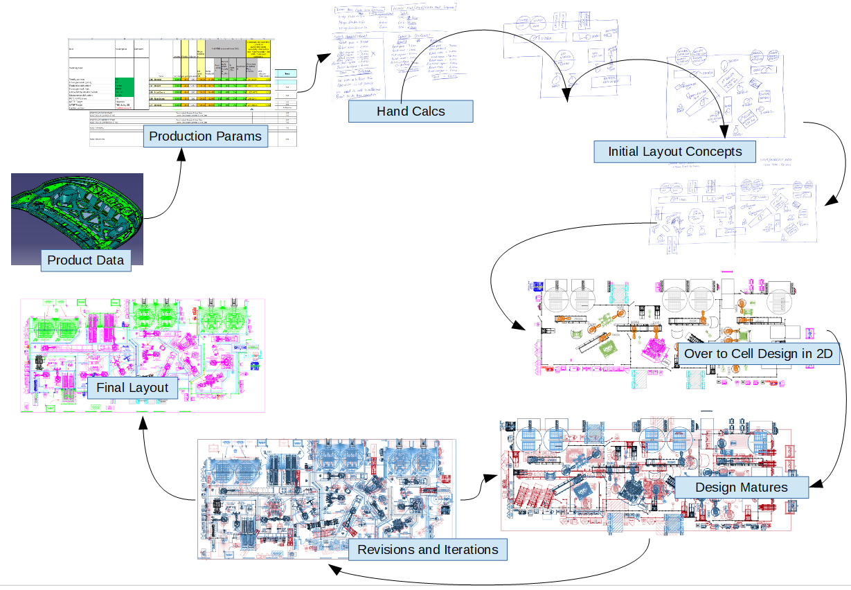
In order to better understand these issues, let us take a look at the steps involved in a typical Plant Layout and Planning process for the manufacture of a car hood.
The process is characterised by the following:
- Relies heavily on the expertise of the planner, and is highly subjective.
- Many options have to be explored, often using hand calculations early on in the design cycle.
- Even when there are no input changes, the process is highly iterative.
- Upstream input changes simply add another dimension to the complexity.
- Difficult to incorporate changes when the layout design has matured.
- Difficult to explore the design space systematically.
- Better alternatives might still exist, but no effort is put to relook from the begining.
Exhibit 1: Plant Layout Planning Process

Exhibit 2: Panel data of a typical Hood Assembly
Typically the starting input is the Panel data. Many a times, the surfaces, especially the joining surfaces are not well defined. Also the joining information is often incomplete or not well defined at this early stage.
Exhibit 3: Overall Process Flow
The planner decides on a build sequence and forms a process flow.
In this case, the Inner and Outer Sub-Assemblies are built separately and brought to the marriage station, from where there will be sealing applied and then later, they are hemmed. A suitable Hemming Methodology is decided based on cycle time and available equipment.


